- 您现在的位置:买卖IC网 > Sheet目录233 > LT1701-7 (Power-One)AC-DC BATTERY CHARGER 54.5V 10A
�� ��
��
��T� Series� Data� Sheet�
�?�
�Control� Features� of� the� Battery� Chargers�
�500� Watt� AC-DC� Converters�
�06068�
�2.23� V� 2.24� V�
�According� to� the� recommendations� of� battery� manufacturers,�
�the� float-charge� voltage� of� lead-acid� batteries� should� be�
�0�
�2.25� V�
�2.26� V�
�temperature-compensated.� Depending� on� the� battery� type� and�
�size,� charging� with� different� temperature� coefficients� may� be�
�2.35� V�
�C�
�4�
�2.27� V�
�required.� An� excessive� float-charge� voltage� may� damage� the�
�2.28� V�
�battery� through� overcharging.�
�8�
�2.29� V�
�Most� lead-acid� battery� manufacturers� recommend� cell�
�voltages� between� 2.23� V� and� 2.32� V,� with� the� nominal� cell�
�voltage� defined� at� 20� °C� and� temperature� coefficients� per� cell�
�between� –3� and� –4� mV/K.�
�2.32� V�
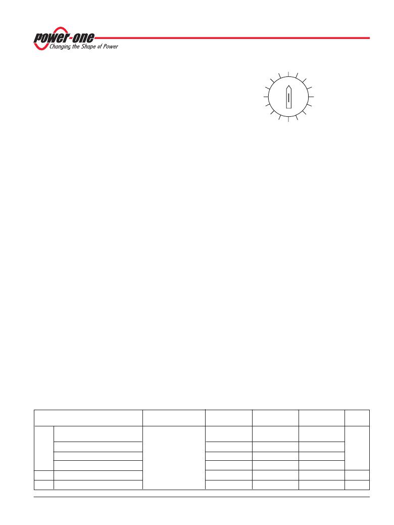
�Fig.� 15�
�Cell� voltage� selector� switch�
�2.31� V�
�2.30� V�
�The� value� of� the� negative� temperature� coefficient� is� specified�
�by� the� type� of� T� temperature� sensor.�
�With� the� cell� voltage� selector� switch� Z,� the� required� cell� voltage�
�can� be� adjusted� at� the� rear� of� the� converter,� making� the� system�
�flexible� to� different� float-charge� voltages.� If� the� selector� switch�
�Z� is� not� applicable,� a� cell� voltage� adjustment� can� also� be�
�provided� by� the� temperature� sensor;� see� Temperature� Sensor�
�T� ).�
�Although� it� is� not� recommended,� the� output� voltage� can� be� set�
�to� a� fixed� value� without� temperature� compensation� by� an�
�external� voltage� source� or� a� resistive� voltage� divider� at� the�
�remote� control� input,� for� instance� if� the� battery� temperature�
�shall� be� controlled� by� other� systems;� see� External� Output�
�Voltage� Control� .�
�Cell� Voltage� Selector� Switch� Z�
�The� battery� chargers� are� equipped� with� the� cell� voltage�
�selector� switch� at� the� rear� side,� which� provides� an� easy� way� of�
�external� adjustment� to� the� required� float-charge� voltage.� Each�
�switch� position� allows� a� step� in� the� output� voltage� of� 10� mV� per�
�cell,� whereby� the� switch� position� "0"� represents� a� cell� voltage�
�of� 2.23� V� at� 20� °C;� position� "C"� gives� 2.35� V� per� cell.�
�The� cell� voltage� selector� switch� fits� together� with� the� 2.23� V�
�temperature� sensor.� The� float-charge� voltage� is� set� by� the�
�switch,� and� the� temperature� coefficient� is� specified� by� the�
�sensor� type.�
�Caution:� Setting� the� switch� to� the� correct� battery� cell� voltage� is�
�vital� for� the� proper� operation� of� a� battery� system.�
�Note:� Switching� to� a� different� cell� voltage� while� the� battery� charger�
�is� operating� may� cause� a� short� distortion� of� the� output� voltage.�
�Potentiometer� for� Fine� Tuning�
�The� battery� chargers� are� equipped� with� a� one-turn�
�potentiometer� for� fine� tuning� of� the� output� voltage� to� within�
�±3.7� 0� /� 00� of� V� o� .� The� potentiometer� is� protected� by� a� plastic�
�cover.� To� adjust� the� output� voltage� for� improved� current�
�sharing� or� compensation� for� voltage� drops� over� the� load� lines,�
�each� battery� charger� in� a� system� should� be� unplugged� and�
�adjusted� individually� to� the� same� output� voltage� at� equal� load;�
�otherwise� current� sharing� may� adversely� be� affected.�
�External� Output� Voltage� Control�
�The� i/Vcr� control� input� (pin� 28)� provides� two� functions:�
�–� External� adjustment� of� the� output� voltage�
�–� Inhibiting� of� the� converter.�
�A� voltage� <0.4� V� inhibits� the� output,� a� voltage� >2.5� V� enables� it.�
�With� the� i/Vcr� input� in� the� range� of� 5.5� V� to� 11.5� V,� the� output�
�voltage� V� o� set� can� be� adjusted� within� a� range� of� +3.6%� to�
�–7.9%.� This� feature� is� optimized� to� control� the� float-charge� of� a�
�lead� acid� batteriy.�
�Outside� of� the� control� range,� the� sensor� monitoring� circuit�
�generates� a� system� error� signal� (see� also� System� Good).�
�In� the� case� of� a� excessively� high� control� voltage,� the� output�
�voltage� is� reduced.�
�The� remote� control� input� is� protected� against� DC� overvoltage�
�up� to� 60� V.�
�Note:� An� open� inhibit/Vcr� remote� control� input� leads� to� a� sensor�
�error� signal� which� is� indicated� by� the� Error� LED� at� the� front� and�
�high� impedance� of� the� "System� good"� signal.� The� output� voltage� is�
�reduced� to� V� cr� fail� condition.�
�Table� 8:� Characteristics� of� the� remote� control�
�Characteristics�
�Conditions�
�LT/UT1240�
�LT1840�
�LT/UT1740�
�Unit�
�typ�
�typ�
�V� o�
�Output� voltage� at:�
�Voltage� selector� switch�
�25.25�
�37.85�
�50.5�
�V�
�V� cr� fail� 2.5� –� 5.5� V�
�Z� set� at� 2.23� V/cell� or�
�V� cr� control� 5.5� –� 11.5� V�
�V� cr� clamp� 11.5� –� 14� V�
�V� cr� fail� 14� –� 60� V�
�without� selector� switch� Z�
�selector� switch� Z�
�V� i� nom� ,� 0.5� ?� I� o� nom�
�22.5� +� V� cr� ?� 0.5�
�28.25�
�25.25�
�22.5� +� V� cr� ?� 0.5�
�42.37�
�37.85�
�45� +� V� cr�
�56.5�
�50.5�
�R� cr�
�f� cr�
�Input� impedance�
�Frequency� limit�
�1�
�1�
�1�
�1�
�1�
�1�
�M� ?�
�Hz�
�BCD20023� Rev� AB,� 02-Nov-2010�
�Page� 11� of� 31�
�www.power-one.com�
�发布紧急采购,3分钟左右您将得到回复。
相关PDF资料
LT5400AIMS8E-3#PBF
RES ARRAY MULT OHM 4 RES 8-MSOP
LTA201-TR-B/125N
SWITCH ROCKER SPST 15A 125V
LTA211-TR-W/125N
SWITCH ROCKER SPST 15A 125V
LUS001ST
SWITCH PUSH SPST-NO 0.25A 28V
LW3021A
SWITCH ROCKER DPST 20A 110V
LW3123-N4EE-H
SWITCH ROCKER DPDT 10A 125V
LXES1TBAA2-013
CERAMIC ESD DEV .55PF 6V SMD
LXES1TBAA4-005
CERAMIC ESD DEV 1.3PF 6V SMD
相关代理商/技术参数
LT1702-7
功能描述:AC-DC BATTERY CHARGER 48V 11A RoHS:否 类别:电源 - 外部/内部(非板载) >> AC DC 转换器 系列:* 产品培训模块:MP Modular-Configurable AC-DC Power Supply 特色产品:Configurable Power Supplies 标准包装:1 系列:MP
LT170A
制造商:未知厂家 制造商全称:未知厂家 功能描述:Linear Hall-Effect Sensor
LT170E2
制造商:未知厂家 制造商全称:未知厂家 功能描述:LT170E2 |Data Sheet
LT170Z
制造商:SEOUL 制造商全称:Seoul Semiconductor 功能描述:GREEN OVAL LAMP LED
LT171
制造商:SEOUL 制造商全称:Seoul Semiconductor 功能描述:RED LAMP LED
LT1711
制造商:未知厂家 制造商全称:未知厂家 功能描述:UNDERSTANDING THE SUBJECT IS CUSTOMER SERVICE
LT1711CMS8
功能描述:IC COMP R-RINOUT SINGLE 8-MSOP RoHS:否 类别:集成电路 (IC) >> 线性 - 比较器 系列:UltraFast™ 产品培训模块:Lead (SnPb) Finish for COTS
Obsolescence Mitigation Program 标准包装:2,500 系列:- 类型:通用 元件数:1 输出类型:CMOS,推挽式,满摆幅,TTL 电压 - 电源,单路/双路(±):2.5 V ~ 5.5 V,±1.25 V ~ 2.75 V 电压 - 输入偏移(最小值):5mV @ 5.5V 电流 - 输入偏压(最小值):1pA @ 5.5V 电流 - 输出(标准):- 电流 - 静态(最大值):24µA CMRR, PSRR(标准):80dB CMRR,80dB PSRR 传输延迟(最大):450ns 磁滞:±3mV 工作温度:-40°C ~ 85°C 封装/外壳:6-WFBGA,CSPBGA 安装类型:表面贴装 包装:管件 其它名称:Q3554586
LT1711CMS8#PBF
功能描述:IC COMP R-RINOUT SINGLE 8-MSOP RoHS:是 类别:集成电路 (IC) >> 线性 - 比较器 系列:UltraFast™ 标准包装:1 系列:- 类型:通用 元件数:1 输出类型:CMOS,开路集电极,TTL 电压 - 电源,单路/双路(±):2.7 V ~ 5.5 V 电压 - 输入偏移(最小值):7mV @ 5V 电流 - 输入偏压(最小值):0.25µA @ 5V 电流 - 输出(标准):84mA @ 5V 电流 - 静态(最大值):120µA CMRR, PSRR(标准):- 传输延迟(最大):600ns 磁滞:- 工作温度:-40°C ~ 85°C 封装/外壳:SC-74A,SOT-753 安装类型:表面贴装 包装:剪切带 (CT) 产品目录页面:1268 (CN2011-ZH PDF) 其它名称:*LMV331M5*LMV331M5/NOPBLMV331M5CT